20220916.5
The ESP32 board costs less than S$5 and the 128x64 OLED tied to it costs less than S$3.
I have to buy the 1-metre USB C cable for this board. It costs less than S$3.
The items took one to two weeks to arrive. But I can wait.
It would be nice if I can program the board in C. But it is quite difficult.
So, I have to settle for micro-python.
20220917.6 IDE
After getting the board, it is usually necessary to flash the MicroPython firmware to the ESP32.
This procedure is described in the site:
Flash/Upload MicroPython Firmware to ESP32 and ESP8266 | Random Nerd Tutorials .
The uPyCraft IDE installed, as described, will also be used in programming the ESP32.
For the board shown above, it is also necessary to install the CH340 driver.
Then the board can be connected to the computer and the firmware flashed to the ESP.
Using the uPyCraft IDE requires some exploration. For example, clicking Help|Tutorial online will lead to a guide on MicroPython for the ESP32, in Chinese.
With the board connected, it is easy to test the programming using the example blink.py(File|Eaxmples|Basic|blink.py) which will blink the LED on the board.
The LED is usually connected to GPIO2 of the ESP32. If the LED is connected to another GPIO pin, it is then necessary to edit the blinky.py file. Besides, the LED may be turned on by either 1 or 0 at the GPIO pin. This may be verified by editing the blinky.py to always output 1 or always output 0.
The program (code) blink.py may be saved on the computer using another name, for example Test1. If Test1 is opened and tested, the same result will be obtained. If the board is disconnected from the computer and then powered up again, the program does not run. However, if the program is saved as main, opened and downloaded, it will run correctly if disconnected and repowered.
20220918.7 GPIO
A very short program would be:
from machine import Pin
led=Pin(2,Pin.OUT)
led.value(1)
The example blink.py uses built-in function 'time'. This can be replaced with a software delay as:
from machine import Pin
led=Pin(2,Pin.OUT)
while True:
led.value(1) #Set led turn on
k = 0
while k<10000:
k = k + 1
led.value(0) #Set led turn off
k = 0
while k<10000:
k = k + 1
20220919.1
The blink.py program can be easily used to test other GPIO pins, as the naming of pins can be quite confusing. Some pins, such as GPIO35, are for input only. This requires an LED and a resistor on a breadboard.
Although one GPIO pin is usually used in a particular situation, occasionally several outputs may be required at one time. For testing purpose, several bits may have to be observed at the same time.
20220921 SPI
The SPI and a shift register 74164 can easily provide 8 outputs to LED's. The program code is simple:
from machine import Pin, SPI
hspi = SPI(1, 10000000) # sck=Pin(14), mosi=Pin(13)
hspi.read(1, 0x53)
Some LED display can be easily tested:
import time
from machine import Pin, SPI
hspi = SPI(1, 10000000) # sck=Pin(14), mosi=Pin(13)
hspi.read(1, 0xAC)
k = 0
while True:
time.sleep(0.1)
hspi.read(1, k)
k = k + 1
if k>255:
k = 0
20220923.5 I2C
More readable information used to be displayed via the alphanumeric dot matrix 2x16 LCD.
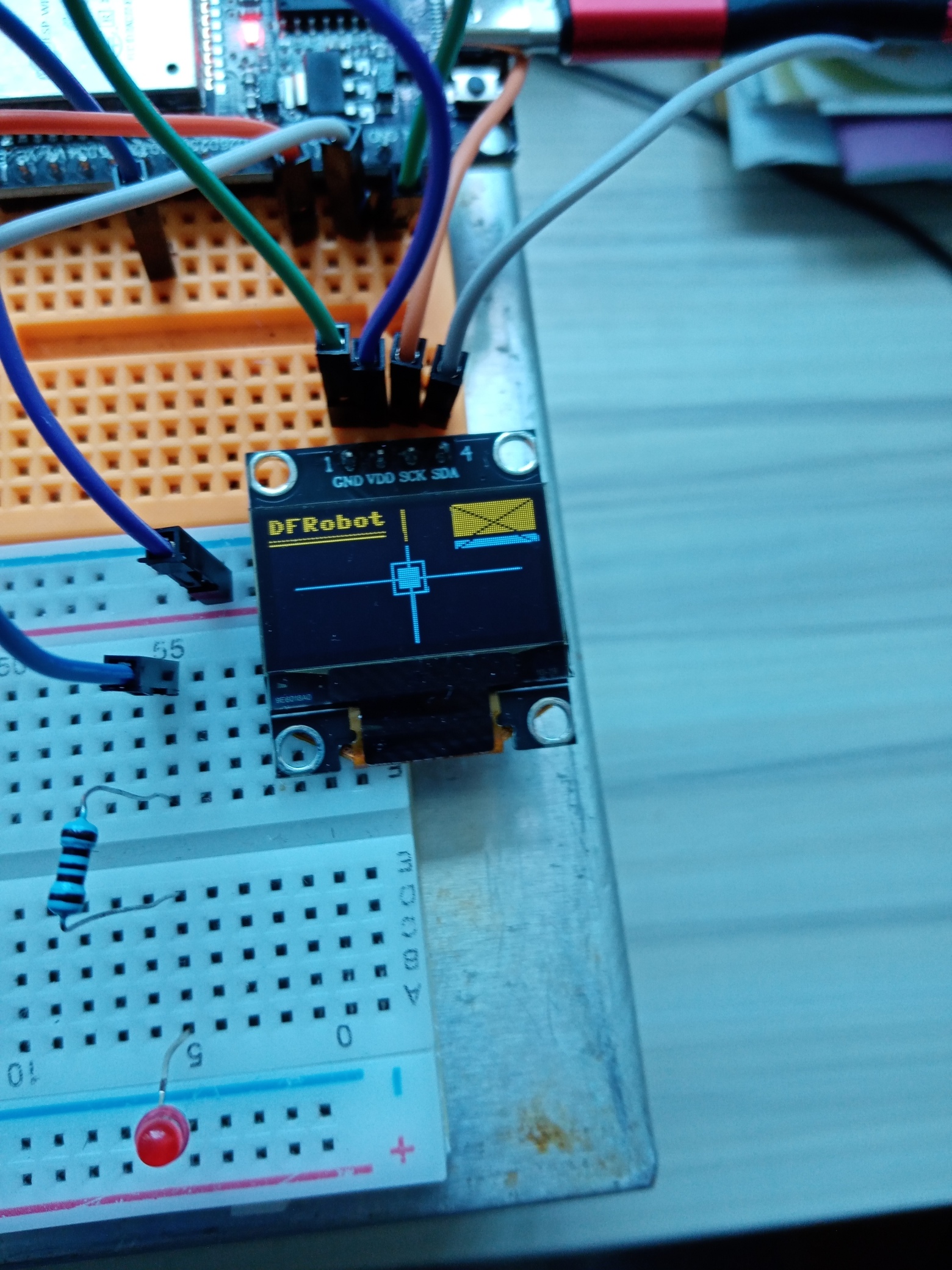
However, with the SSD1306 library on the uPyCraft IDE, it is relatively easy to use a 128x64 OLED.
The ssd1306.py has to be flashed onto the board before the functions can be called.
A simple test can be used to check the connections, where the I2C pins may be freely chosen.
from machine import Pin, SoftI2C
import ssd1306
i2c = SoftI2C(sda=Pin(4), scl=Pin(5)) # using default address 0x3C
display = ssd1306.SSD1306_I2C(128, 32, i2c)
display.text(' ESP32 KCS', 8, 8, 1)
display.show()
This display is obtained with the OLED defined as 128 x 32, so the texts appear larger.
The uPyCraft IDE contains an example for the OLED as shown here, with codes modified.
The codes below show that the 128x64 OLED can display 128 small characters:
from machine import Pin, SoftI2C
import ssd1306
led = Pin(2, Pin.OUT)
# using default address 0x3C
i2c = SoftI2C(sda=Pin(4), scl=Pin(5))
display = ssd1306.SSD1306_I2C(128, 64, i2c)
#display.text('Hello, World!', 0, 0, 1)
line1 = '1234567890123456'
line2 = '234567890123456'
line3 = '34567890123456'
line4 = '4567890123456'
line5 = '567890123456'
line6 = '67890123456'
line7 = '7890123456'
line8 = '8901234567890123'
display.text(line1, 0, 0, 1)
display.text(line2, 0, 8, 1)
display.text(line3, 0, 16, 1)
display.text(line4, 0, 24, 1)
display.text(line5, 0, 32, 1)
display.text(line6, 0, 40, 1)
display.text(line7, 0, 48, 1)
display.text(line8, 0, 56, 1)
display.show()
while True:
led.value(0) # ON
20220925 Timer interrupt
The example blink.py uses built-in function 'time':
import time
from machine import Pin
led=Pin(2,Pin.OUT) #create LED object from pin2,Set Pin2 to output
while True:
led.value(1) #Set led turn on
time.sleep(0.5)
led.value(0) #Set led turn off
time.sleep(0.5)
But to keep blinking an LED this way would not allow the microcontroller to do other things.
So, interrupt procedures are required. The interrupt service routine blinks the LED while the main program can perform other duties.
from machine import Pin, Timer
import time
led=Pin(2,Pin.OUT)
led3=Pin(32,Pin.OUT)
Count = 0
def tisr(tim0):
global Count
Count = Count + 1
led.value(Count%2)
tim0 = Timer(0)
tim0.init(period=1000, mode=Timer.PERIODIC, callback=tisr)
while True:
led3.value(1)
time.sleep(0.1)
led3.value(0)
time.sleep(0.1)
As Timer0 is activated, the program can be edited to display its value at regular intervals:
from machine import Pin, Timer
import time
from machine import mem32
from micropython import const
Timer0L = const(0x3FF5F004)
Timer0H = const(0x3FF5F008)
T0Latch = const(0x3FF5F00C)
led=Pin(2,Pin.OUT)
led3=Pin(32,Pin.OUT)
Count = 0
def tisr(tim0):
global Count
Count = Count + 1
led.value(Count%2)
tim0 = Timer(0)
tim0.init(period=1000, mode=Timer.PERIODIC, callback=tisr)
while True:
led3.value(1)
time.sleep(0.1)
led3.value(0)
time.sleep(0.1)
mem32[T0Latch] = 0x55
print(hex(mem32[Timer0H]), hex(mem32[Timer0L]))
The following shows some print-out:
0x0 0x3e15d4
0x0 0x5cc069
0x0 0x7b6af2
0x0 0x17edc
This procedure is possible because the board is communicating with the IDE through the serial port. This is an advantage of the micropython approach.
The register addresses are obtained from the technical manual.
The higher 32-bit half is always zero.
The lower 32-bit half is changing rapidly, which depends on how the Timer0 is set up for the 1-second interrupt.
202209


Comments
Post a Comment