ATmega16KCS

20221007.5

Continue from: Programming Microcontrollers: ATMEGA16A (programmingmicrocontrollerskohcs.blogspot.com)

IAR Embedded Workbench for Microchip AVR 7.30.5

AVRDUDESS 2.14


20221008.6


This would be a rather straight forward set up for the hardware.

Although it is a continuation, some rewriting may be useful.

IAR Embedded Workbench

            Create a New C main Project

            Select ATmega16 as the processor

            Select ‘Other’ for the linker output

            Make the active project


AVRDUDESS

            Select the appropriate programmer

            Detect the MCU

            Open the ‘.90’ file produced by the Workbench

            Flash the file to the ATmega16

                        Some 100+ bytes would be written.


20221009.7

The following program would toggle an LED (with a series resistor) connected to Port A bit 0.

//  AT01LEDt    Toggle Port A bit 0     iRC 1 MHz 

#include <iom16.h>

int main( void )

{

  int i;

  PORTA &= ~0x01 ;      // clear Bit 0 

  DDRA  |= 0x01 ;       // Bit 0 Output

  while(1){

    for(i=0;i<=30000;i++){;}    // Do not exceed 32767

    PORTA |= 0x01 ;             // set Bit 0 

    for(i=0;i<=30000;i++){;}  

    PORTA &= ~0x01 ;            // clear Bit 0 

  }

}

This is assuming that the MCU is running at 1-MHz with the default Fuse Low Byte of 0xE1.

The Fuse Low Byte can be written with 0xE4 to change the clock to 8 MHz.

The LED would then blink rapidly.

To blink the LED more slowly, the software delay has to be lengthened.

Alternatively, timer interrupt can be used.


20221009.7b

The following program uses Timer 1 to produce a 0.5-second interrupt. (8000000/256=31250)

On interrupt, the LED would toggle, lighting up at the rate of 1 Hz approximately.

//  AT03T1OCIA    Timer1 OC Interrupt A         iRC 8 MHz


#include <iom16.h>

#include <intrinsics.h>

  int c;

int main( void )

{

  PORTA &= ~0x01 ;      // clear Bit 0 

  DDRA  |= 0x01 ;       // Bit 0 Output


  __disable_interrupt();

  TCCR1A = 0x00 ;       // Normal

  TCCR1B = 0x0C ;       // CTC1, prescaler 256  

  TIMSK |= 0x10 ;       // 0x10 is OCIE1A

  OCR1A = 31250/2 ;     // 0.5-second interrupt

  __enable_interrupt();  


  c = 0 ;

  while(1);

}


/* Interrupt handler for the TIMER1_COMPARE vector. */

#pragma vector=TIMER1_COMPA_vect

__interrupt void T1OCA_Handler(void){

  if(c==1){

            PORTA |= 0x01 ;

            c = 0 ;

          }

    else  {

            PORTA &= ~0x01 ;

            c = 1;

          }    

}


20221105.6

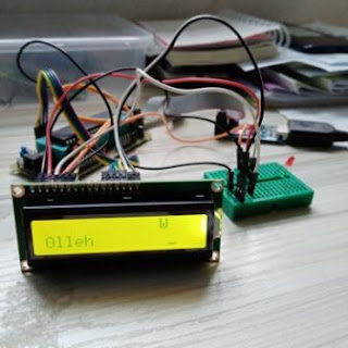
This follows T31 of the previous blog listed above, with the same connections:
               ATMEGA16           LCD 1602
               Port D bits 7,6,5,4  Data bits 7,6,5,4
               Port A bit 1             RS
               Port A bit 0             E
                                              W/R connect to Ground
                                              Vo connect to Ground through a 1-k resistor

It is obvious that such LCD should be controlled using just 4 wires only for the data bus.
The program is re-written as follows:
// AT05LCDh2
#include <iom16.h>
#include <intrinsics.h>

void LCD_W(int RS,int DATA,int T);
           
int main(){
  unsigned int i ;
  unsigned char seq[]={0x33,0x33,0x32,0x28,0x0F,0x06,0x01};
  unsigned char str[]={'O','l','l','e','h',' ',' ',' ',' ',' ',' ',' ',' ',' '};
    
  PORTA &= ~(1<<0) ;    // Bit 0 clear    E = 0
  DDRA  |= 1<<0 ;       // Bit 0 Output
  PORTA &= ~(1<<1) ;    // Bit 1 clear    RS = 0
  DDRA  |= 1<<1 ;       // Bit 1 Output
  PORTD = 0x00 ;
  DDRD |= 0xF0 ;        // 7,6,5,4  Output

  for(i=0;i<=6;i++){ LCD_W(0,seq[i],1000); }

  for(i=0;i<=50000;i++);      // Give time for clear screen

  LCD_W(0,0x8C,1000); 
  LCD_W(1,'W',1000);

  LCD_W(0,0xC0,1000); 
  for(i=0;i<=12;i++){ LCD_W(1,str[i],1000); }

  while(1);     // Wait for interrupts
}

void LCD_W(int RS,int DATA,int K){
  int i ;
    if(RS==0) PORTA &= ~(1<<1) ;    // Bit 1 clear    RS = 0
         else PORTA |=  (1<<1) ;    // Bit 1 set    RS = 1
    PORTD = DATA&0xF0 ;  
    for(i=0;i<=K;i++){ ; }      
    PORTA |=  (1<<0) ;    // Bit 0 set      E = 1
    for(i=0;i<=K;i++){ ; }
    PORTA &= ~(1<<0) ;    // Bit 0 clear    E = 0
    PORTD = DATA<<4 ;
    for(i=0;i<=K;i++){ ; }      
    PORTA |=  (1<<0) ;    // Bit 0 set      E = 1
    for(i=0;i<=K;i++){ ; }
    PORTA &= ~(1<<0) ;    // Bit 0 clear    E = 0
}


202210


Comments

Popular posts from this blog

CH32V307KCS

PyBoard405KCS

ESP32KCS